top of page

HEATBIND™

for VPX per ANSI/VITA 46.0-2023, 48.2-2022 & 78.0 2022

Heatbind 0BG

Listed in this section:

  1. HEATBIND™ Plug-In Module (PIM) Top Part Number Configuration Table.

  2. Part numbers of complete retainer kits.

  3. ​Part numbers of blind-mating keying kit.

  4. Part number of injector/ejector lever kit.

  5. Part number of backplane blind-mating guide.

  6. Representative figures.

  7. Part number configuration form and quote request.

VPX - PIM (Plug-In Module) Top - Part Number Configuration Overview

VPX PIM Part Number Configurator
Primary side solid retainer kit

VPX Primary Side Retainer Kit Part Number: RPBK1112ZZB

394W/mxK

secondary side solid retainer kit

VPX Secondary Side Retainer Kit Part Number: RSBK1112ZZB

394W/mxK

Integrated blind-mating guides
KBBK4000ZZB

VPX 3U Integrated Keying and Grounding Kit Part Number: KBBK4000ZZB

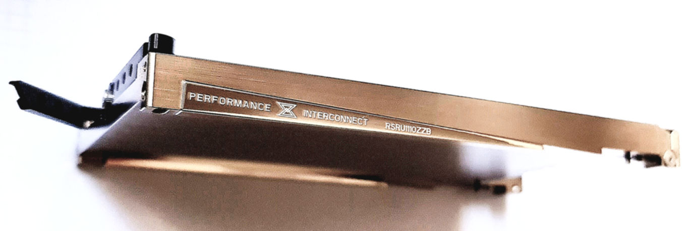
PIM Top with HEATBIND™ solid retainers on secondary side. Supplied solid at top of PCB. Customer to machine skyline. All accessories are kitted separately based on customer's selection in the part number configurator.

HEATBIND™ Retainers on Secondary Side
LKBKXXXCZZB

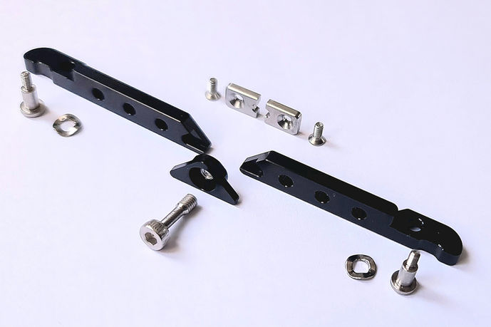
3U VPX Injector/Ejector Kit with Keystone Lock: LKBKXXXCZZB

KBBUB370ZZB

Machined backplane guide pin: KBBUB370ZZB

Note:
Base material is brass, not susceptible to whisker growth, non-magnetic, residual magnetism < 5 gamma.
Gold finish for space-flight application is available.

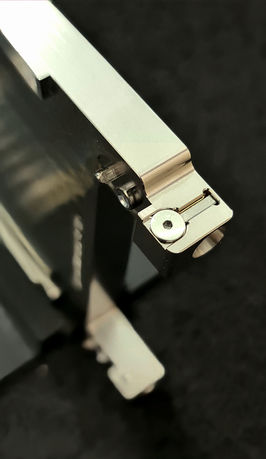
Injector/Ejector Levers with Keystone Lock - Permits User to easily manipulate insertion and extraction of PIM during testing and lock the levers with a clear visual indicator after final installation.

HEATBIND Plug-In Module with Opened
HEATBIND Plug-In Module with Levers Unlocked
HEATBIND Plug-In Module with Levers Locked

3U Plug-In Module Top with HEATBIND™ Solid retainers on Secondary Side and Integrated Blind-Mating Guide Sockets with User Selectable Keying. Part number Example: TSCU2412PIB.
Note, backplane guides and other accessories are separate kits, not included in part number.

TSCU2412PIB
Sample.png

REQUEST A SAMPLE TO TEST AND DISCOVER THE BEST THERMAL INTERCONNECT SYSTEM AVAILABLE ANYWHERE!

VPX - PIM Top - Part Number Configuration Tool & Quote Request
The following form allows you to configure your plug-in module top in 10 easy steps and request a quote.

STEP 1: COMPONENT NAME

T = Plug-In Module Top for VPX

STEP 2: POSITION OF RETAINERS

P = Integrated Retainer Ramps on PRIMARY Side

S = Integrated Retainer Ramps on SECONDARY Side

STEP 3: WIDTH OF MODULE

C = 3U module width

H = 6U module width

STEP 4: COMPONENT DETAIL

U = Unique Part Number

STEP 5: BASE MATERIAL DEFINITION

1 = PIM Base Material is OFC Copper C10200, Tc=394W/mK

2 = PIM Material is Aluminum 6063, Tc=200W/mK

E = PIM Base Material is specific per customer drawing

STEP 6: SURFACE FINISH QUALITY

4 = Surface finish Ra≤0.4µm

E = Specific Finish Requirement per Customer drawing

STEP 7: SURFACE FINISH TREATMENT

1 = HIGH PHOSPHORUS ELECTROLESS NICKEL per MIL-C-26074 CLASS 4, ASTM B733, min 10.2µm PLATING THICKNESS. PLUG ALL THREADED HOLES PRIOR TO PLATING.

3 = BLACK HARD ANODIZING per MIL-A-8625 - TYPE 2, CLASS 2. PLUG ALL THREADED HOLES PRIOR TO ANODIZING.

7 = Nickel electroplate, fully bright, 6.35µm thick, over Copper electroplate, 2.54µm thick.

8 = Hexavalent Chromium Chromate Conversion Coating to meet Mil-C-5541A standard. Restricted for some applications.

9 = Trivalent Chromium Chromate Conversion

STEP 8: COMPLIANCE DESIGNATOR

2 = Per Details in PISAS Drawing: BLIND-MATE GUIDES and INJ-EJECTOR mounting features ARE INCLUDED.

3 = Per Details in CUSTOMER Drawing, up to 18mm PIM Top thickness.

4 = Per Details in PISAS Drawing: INJ-EJECTOR mounting features ARE INCLUDED, BLIND-MATE GUIDES are NOT INCLUDED.

5 = Per Details in PISAS Drawing: BLIND-MATE GUIDES ARE INCLUDED, INJ/EJECTOR mounting features are NOT INCLUDED.

6 = Per Details in PISAS Drawing: BLIND-MATE GUIDES and INJ/EJECTOR mounting features are NOT INCLUDED.

STEP 9: 2-DIGIT ENTITY CODE

PI = Performance Interconnect part. Solid material to top of PCB, customer to machine skyline.

00 = Indicates Custom Part with machined skyline - 00 to be replaced with Customer-Specific 2-Letter Designation.

STEP 10: PRODUCT GROUP DESIGNATOR

B = HEATBIND Product Group

Quantity to be quoted

Multiple options may be chosen in this section.

NOTE: Prototype purchases shall be fully credited towards production quantity purchases.

HEATBIND™ Solid Retainer Kits
Primary side retainers kit: RPBK1112ZZB
Secondary side retainers kit: RSBK1112ZZB

Select retainer kit part number to be quoted according to Step 2 above.

Additional Options - Check box to add items to your quote

Kits shall be quoted by default if the option was chosen in Step 8 above.

Keyed Backplane guide - standard part shown. Variations are available upon request.


Please add your relevant comments in this section

SUBSCRIBE

Sign up to receive Performance Interconnect news and updates.

Thanks for submitting!

©2025 All Rights Reserved.

PERFORMANCE INTERCONNECT SAS,

478 Rue de la Découverte, Mini Parc 3 - CS67624, 31676, LABEGE cedex, FRANCE

- société par actions simplifiée à capital variable - SIRET 919 133 983 00016

SIREN 919 133 983 EORI FR91913398300016

Member of:

Member of VITA organization
bottom of page